Тьерри Мейссан - 11 сентября 2001

- Название:11 сентября 2001
- Автор:
- Жанр:
- Издательство:Карно
- Год:2002
- Город:Москва
- ISBN:нет данных
- Рейтинг:
- Избранное:Добавить в избранное
-
Отзывы:
-
Ваша оценка:
Тьерри Мейссан - 11 сентября 2001 краткое содержание
Эта книга произвела фурор и мгновенно стала бестселлером во Франции, а затем и в других европейских странах. В США власти более года препятствовали выходу в свет этой книги, но она все же была опубликована – и сразу стала мощнейшим подспорьем для антивоенного и «антиглобалистского» движения. То, что книга Мейссана не только не стала бестселлером у нас в стране, а, напротив, была фактически замолчана, – явление позорное, говорящее о продажном, марионеточном, характере политической науки в России.
11 сентября 2001 - читать онлайн бесплатно полную версию (весь текст целиком)
Интервал:
Закладка:
• In order to explain why the towers collapsed, where other steel framed buildings would have survived, the WTC conspirators invented the «truss theory».
• The «truss theory» is seriously flawed. It cannot explain how the perimeter wall transmits wind loading to the central core.
• The «truss theory», if accepted, leads to a 33 percent underestimate of the amount of steel in the towers. That is, the «truss theory» does not account for the whereabouts of 32,000 tons of steel (of 96,000 tons) used in the construction of each of the towers.
• The «truss theory» is a lie that has been spun to convince a gullible public, that what appeared to be the controlled demolitions of three of the World Trade Center buildings, were actually natural consequents of the aircraft strikes and not controlled demolitions at all.
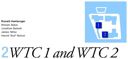
• There are photos showing large steel girders positioned where the «official» line states that only (double) trusses should be.
• In all, one has to conclude that the «truss theory» is false and that those who push it are part of a large conspiracy to deceive the American people.
Architects must provide World Trade Center blueprints and plans
Design architecture for the World Trade Center was provided by Minoru Yamasaki & Associates. Emery Roth & Sons served as the architect of record. Since these people have nothing to hide, they should provide the architectural plans of the World Trade Center, for all to see. This will enable any misunderstandings regarding the facts of the collapse to be established and corrected. In fact, Minoru Yamasaki & Associates, Roth & Sons, or their descendent companies, should put the entire set of architectural plans on the internet.
Официальный отчет
The WTC Report.
2.1 Building Descriptions
2.1.1 General
The WTC towers, also known as WTC 1 and WTC 2, were the primary components of the seven building World Trade Center complex. Each of the towers encompassed 110 stories above the Plaza level and seven levels below. WTC 1 (the north tower) had a roof height of 1,368 feet, briefly earning it the title of the world's tallest building. WTC 2 (the south tower) was nearly as tall, with a roof height of 1,362 feet. WTC 1 also supported a 360-foot-tall television and radio transmission tower. Each building had a square floor plate, 207 feet 2 inches long on each side. Corners were chamfered 6 feet 11 inches. Nearly an acre of floor space was provided at each level. A rectangular service core with overall dimensions of approximately 87 feet by 137 feet, was present at the center of each building, housing 3 exit stairways, 99 elevators, and 16 escalators. Note, that this description of the core is meant to mislead the reader by directing attention away from the cores main purpose, which was to support most, if not all, of the gravity load (weight) of the building and to reduce it to just «an entrance and exit». The core provided the strength needed to support the weight of the structure, while the outer wall provided the necessary rigidity to resist lateral loading due to the wind. Figure 2-1 presents a schematic plan of a representative above ground floor.
The project was developed by the Port Authority of New York and New Jersey (hereafter referred to as the Port Authority), a bi-state public agency. Original occupancy of the towers was dominated by government agencies, including substantial occupancy by the Port Authority itself. However, this occupancy evolved over the years and, by 2001, the predominant occupancy of the towers was by commercial tenants, including a number of prominent financial and insurance services firms.
Design architecture was provided by Minoru Yamasaki & Associates, and Emery Roth & Sons served as the architect of record. Since these companies have nothing to hide, they should provide the architectural plans of the WTC to the world, so that any misunderstandings regarding the facts of the collapse, may be established. In fact, Minoru Yamasaki & Associates, and Roth & Sons, or their descendent companies, should put the entire set of architectural plans on the internet. Skilling, Helle, Christiansen, Robertson were the project structural engineers; Jaros, Baum & Bolles were the mechanical engineers; and Joseph R. Loring & Associates were the electrical engineers. The Port Authority provided design services for site utilities, foundations, basement retaining walls, and paving. Ground breaking for construction was on August 5, 1966. Steel construction began in August 1968. First tenant occupancy of WTC 1 was in December 1970, and occupancy of WTC 2 began in January 1972. Ribbon cutting was on April 4, 1973.
2.1.2 Structural Description
WTC 1 and WTC 2 were similar, but not identical. WTC 1 was 6 feet taller than WTC 2 and also supported a 360-foot tall transmission tower. The service core in WTC 1 was oriented east to west, and the service core in WTC 2 was oriented north to south. Service core, service core,… more propaganda. The more you are told the core is just for servicing the building, the more you believe it. Right ? In addition to these basic configuration differences, the presence of each building affected the wind loads on the other, resulting in a somewhat different distribution of design wind pressures, and, therefore, a somewhat different structural design of the lateral-force-resisting system. In addition, tenant improvements over the years resulted in removal of portions of floors and placement of new private stairways between floors, in a somewhat random pattern. Figure 2-2 presents a structural framing plan representative of an upper floor in the towers.
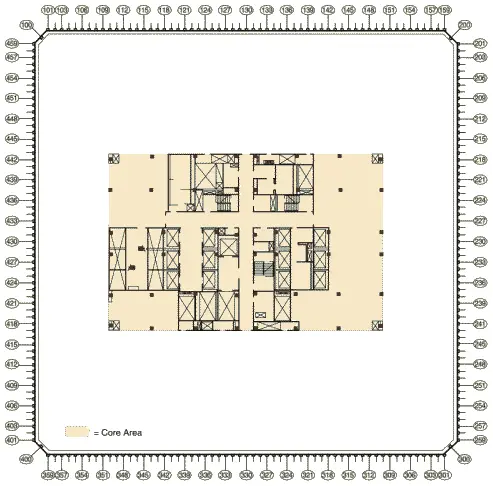
Figure 2-1 Representative floor plan (based on floor plan for 94th and 95th floors of WTC1).
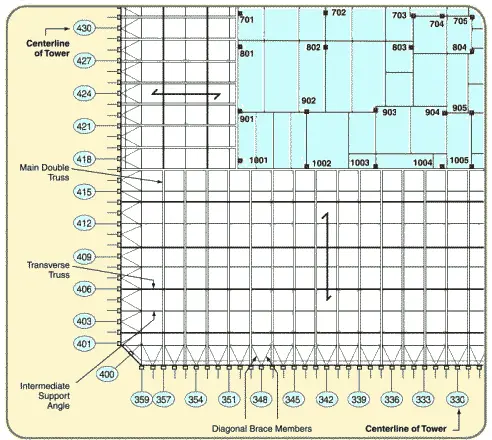
Figure 2-2 Representative structural framing plan, upper floors.
The buildings' signature architectural design feature was the vertical fenestration, the predominant element of which was a series of closely spaced built-up box columns. At typical floors, a total of 59 of these perimeter columns were present along each of the flat faces of the building. These columns were built up by welding four plates together to form an approximately 14-inch square section, spaced at 3 feet 4 inches on center. Adjacent perimeter columns were interconnected at each floor level by deep spandrel plates, typically 52 inches in depth. In alternate stories, an additional column was present at the center of each of the chamfered building corners. The resulting configuration of closely spaced columns and deep spandrels created a perforated steel bearing-wall frame system that extended continuously around the building perimeter.
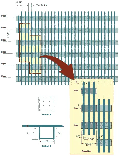
Figure 2-3 Partial elevation of exterior bearing-wall frame showing exterior wall module construction.
Figure 2-3 presents a partial elevation of this exterior wall at typical building floors. Construction of the perimeter-wall frame made extensive use of modular shop prefabrication. In general, each exterior wall module consisted of three columns, three stories tall, interconnected by the spandrel plates, using all-welded construction. Cap plates were provided at the tops and bottoms of each column, to permit bolted connection to the modules above and below. Access holes were provided at the inside face of the columns for attaching high-strength bolted connections. Connection strength varied throughout the building, ranging from four bolts at upper stories to six bolts at lower stories. Near the building base, supplemental welds were also utilized.
Side joints of adjacent modules consisted of high-strength bolted shear connections between the spandrels at mid-span. Except at the base of the structures and at mechanical floors (Figure 2-8 shows one of these mechanical floors. Note that all the perimeter wall columns are joined/spliced at this one level.) horizontal splices between modules were staggered in elevation so that not more than one third of the units were spliced in any one story. Where the units were all spliced at a common level, supplemental welds were used to improve the strength of these connections. Figure 2-3 illustrates the construction of typical modules and their interconnection. At the building base, adjacent sets of three columns tapered to form a single massive column, in a fork-like formation, shown in Figure 2-4.
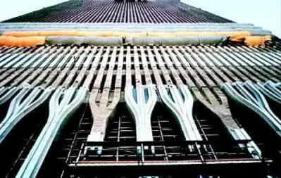
Figure 2-4 Base of exterior wall frame.
Twelve grades of steel, having yield strengths varying between 42 kips per square inch (ksi) and 100 ksi, were used to fabricate the perimeter column and spandrel plates as dictated by the computed gravity and wind demands. Plate thickness also varied, both vertically and around the building perimeter, to accommodate the predicted loads and minimize differential shortening of columns across the floor plate. In upper stories of the building, plate thickness in the exterior wall was generally 1/4 inch. At the base of the building, column plates as thick as 4 inches were used. Arrangement of member types (grade and thickness) was neither exactly symmetrical within a given building nor the same in the two towers. One would definitely be interested in the arrangement of member types, especially whether or not the perimeter wall had columns with say, 2 inch thickness, regularly interspersed among those of 1/4 inch thickness. These would then form the frame of a regular steel-framed building.
The stiffness of the spandrel plates, created by the combined effects of the short spans (Not true. To obtain the required stiffness, the spandrel plates were bolted together to form a very long span. In fact, they spanned right around the building.) and significant depth (True.) created a structural system that was stiff both laterally and vertically. Under the effects of lateral wind loading, the buildings essentially behaved as cantilevered hollow structural tubes with perforated walls. Just think of the perimeter wall as a massive box column, with hundreds of small holes cut in it. In each building, the windward wall acted as a tension flange for the tube while the leeward wall acted as a compression flange. The side walls acted as the webs of the tube, and transferred shear between the windward and leeward walls through Vierendeel action (Figure 2-5).
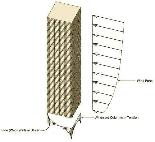
Figure 2-5 Structural tube frame behavior.
Vierendeel action occurs in rigid trusses that do not have diagonals. In such structures, stiffness is achieved through the flexural (bending) strength of the connected members. In the lower seven stories of the towers, where there were fewer columns (Figure 2-4), vertical diagonal braces were in place at the building cores to provide this stiffness. This structural frame was considered to constitute a tubular system.
Читать дальшеИнтервал:
Закладка: